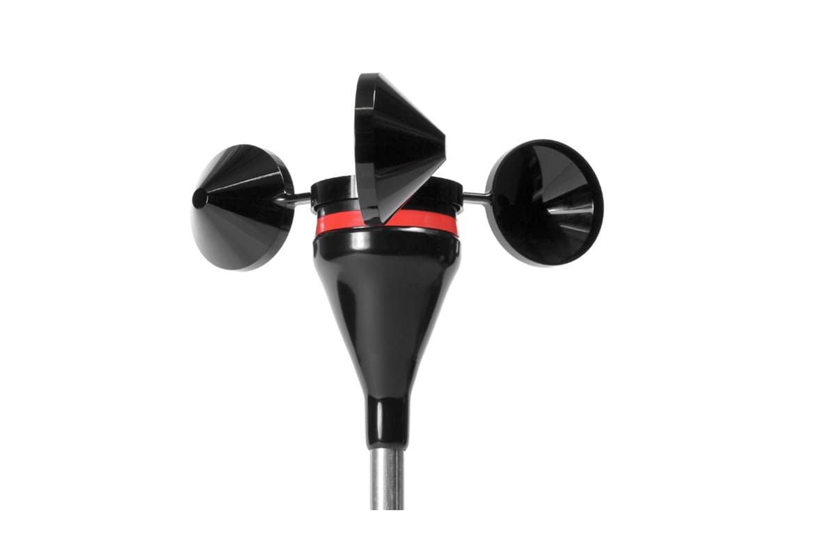
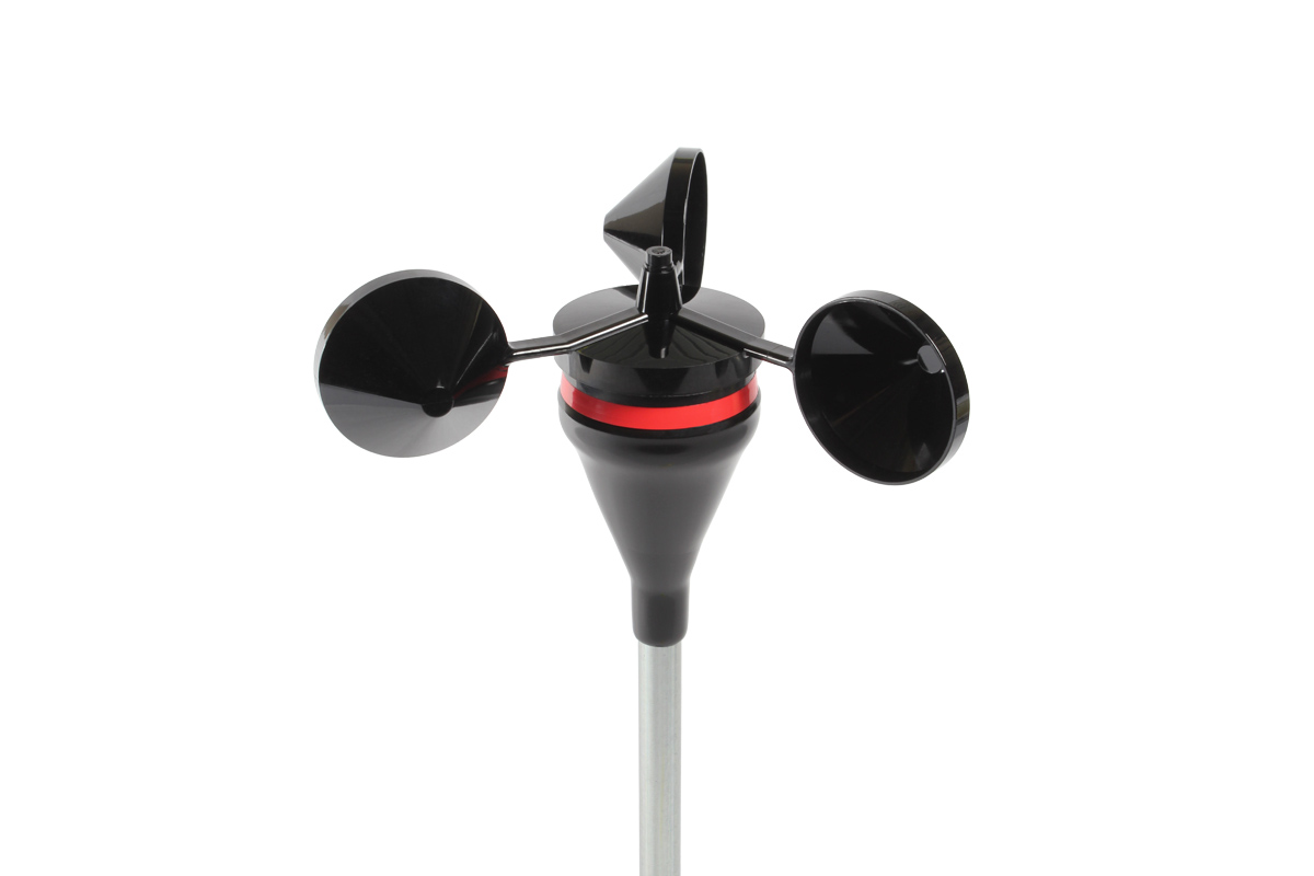
RNRG Class 1 Anemometer
The RNRG Class 1 anemometer is the ideal, low-cost solution for wind resource assessment projects that require an anemometer with class 1A compliance.
The RNRG Class 1 anemometer is the ideal, low-cost solution for wind resource assessment projects that require an anemometer with class 1A compliance.


The NRG Class 1 Anemometer is a ball-bearing version of our industry-leading RNRG 40C Anemometer. That is, it relies upon the same compact external form factor for easy transport and installation. Inside, the patented dual shaft design of the NRG Class 1 protects the bearings from debris and the common impact loads experienced in harsh climates, while the bearings themselves deliver the low friction necessary to achieve certified class 1 performance.
NRG was the first company to obtain endorsement in the classification of an anemometer from Troels Pedersen of the DTU Wind Energy Department. A calibration certificate comes with each sensor, verifying its traceability to the National Institute of Standards and Technology (U.S.A.):
Download Calibration Report.
| MEASNET Calibrated | |
|---|---|
| Description | |
| Sensor type | 3-cup anemometer |
| Applications |
|
| Sensor range | 1 m/s to 96 m/s (2.2 mph to 215 mph) (highest tested) |
| Instrument compatibility | All NRG Systems data loggers |
| Output signal | |
| Signal type | Low level AC sine wave, frequency linearly proportional to wind speed |
| Anemometer Transfer Function |
|
| Output voltage at threshold | 80 mV (peak-to-peak) minimum |
| Output voltage at 60Hz |
|
| Calibration | Each anemometer individually calibrated, calibration reports provided via electronic download |
| Output signal range | 0 Hz to 125 Hz (highest recorded) |
| Uncertainty |
IEC 61400-12-1 Classification
|
| Response characteristics | |
| Threshold | 0.79 m/s (1.77 mph) per ASTM D 5096-02 |
| Distance constant (63% recovery) |
|
| Moment of inertia |
|
| Swept diameter of rotor | 190 mm (7.5 inches) |
| Installation | |
| Mounting | Onto a 13 mm (0.5 inch) diameter mast with cotter pin and set screw |
| Tools required | 0.25 inch nut driver, petroleum jelly, electrical tape |
| Environmental | |
| Operating temperature range | -55 °C to 60 °C (-67 °F to 140 °F) |
| Operating humidity range | 0 to 100% RH |
| Physical | |
| Connections | 4-40 brass hex nut/post terminals |
| Weight | 0.14 kg (0.3 lbs) |
| Dimensions |
|
| Materials | |
| Cups | One piece injection-molded black polycarbonate |
| Body | Housing is electrically conductive black ABS plastic |
| Shaft | Hardened 400 series stainless steel |
| Bearing | Ball bearings |
| Magnet | Indox 1, 25 mm (1 inch) diameter, 13 mm (0.5 inch) long, 4 poles |
| Coil | Single coil, bobbin wound, 4100 turns of #40 wire, shielded for ESD protection |
| Boot | Protective PVC sensor terminal boot included |
| Terminals | Brass |
For product support, details and FAQS on product please visit : click here